Site Logo
part store icon
  • >SMT Equipment
    • Stencil Printers
    • Pick and Place
    • Reflow Ovens
    • PCB Inspection System
    • Custom Equipment
  • >Through-Hole Systems
    • Wave Solder Machines
    • Selective Solder Systems
    • Solder Fountains / Rework
    • Component Counters
    • Lead Formers
  • Industries
    • Contract Manufacturers
    • OEMs
    • Universities
    • Aerospace/Defense/Military
    • R&D/Product Development
  • Support
    • Learning Center
    • Product Training
    • Technical Workshops
    • Service and Support
    • File Library
  • About us
    • Our Team
    • History
    • Customers
    • Made in the USA
    • News and Events
  • Contact Us
Close
  • >SMT Equipment▲
    • Stencil Printers
    • Pick and Place
    • Reflow Ovens
    • PCB Inspection System
    • Custom Equipment
  • >Through-Hole Systems▲
    • Wave Solder Machines
    • Selective Solder Systems
    • Solder Fountains / Rework
    • Component Counters
    • Lead Formers
  • Industries▲
    • Contract Manufacturers
    • OEMs
    • Universities
    • Aerospace/Defense/Military
    • R&D/Product Development
  • Support▲
    • Learning Center
    • Product Training
    • Technical Workshops
    • Service and Support
    • File Library
  • About us▲
    • Our Team
    • History
    • Customers
    • Made in the USA
    • News and Events
  • Contact Us
Home > Support

Support

  • Learning Center
  • Product Training
  • Technical Workshops
  • Service and Support
  • File Library
Made In USA emblem


Selective Soldering

Selective Solder Process Parameters
Selective Solder Quick Start Guide & Tips
Selective Solder Troubleshooting Guide

Introduction

Selective soldering is an automated through-hole method soldering. It is especially useful for avoiding damage to components that are sensitive to the heat of a reflow oven in a traditional SMT assembly process. Selective soldering is also useful for soldering odd size components. Selective soldering may replace or follow a SMT oven reflow process and is a substitute for laborious hand soldering.

To obtain the best process conditions and the highest degree of reliability for selective soldering, consider the following:

  • Pad design type and distance between each other
  • Distance between the component pad and the neighboring component pad (e.g. SMD that you do not want to touch)
  • The pin length under the board
  • The pitch between pins

Methods of selective soldering include dip soldering and drag soldering. Board design needs to be considered depending on which method is selected.

Some recommendations are listed below that will help obtain successful soldering results.

Board Design Characteristics for Selective Soldering Process

Internal Component Clearance

Internal Component Clearance
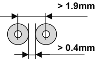
  • Round pads are preferable
  • Distance between round pads should be > 0.4mm
  • Pitch between pins should be > 1.9mm
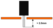
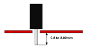
Pin Length Under the Board Pin Length Under the Board
  • The pin length should be 0.8 to 2mm under the board
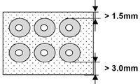
External Clearance Around the Pads External Clearance Around the Pads
  • On 3 sides: > 1.5mm
  • On the 4th side: > 3.0mm (The direction in which the solder is flowing)


Board Design Characteristics for Dragging Solder Process
Internal Component Clearance Internal Component Clearance
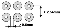
  • Round pads are preferable
  • Space between round pads: > 0.4mm
  • Pitch between pins: > 1.9mm
Pin Length Under the Board Pin Length Under the Board
  • The pin length should be 0.8 to 2mm under the board
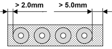
External Clearance Around the Pads External Clearance Around the Pads
  • On 3 sides: > 2.0mm
  • On the 4th side: > 5.0mm (The direction in which the solder is flowing)


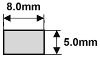
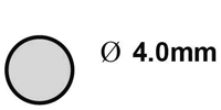
Smallest Dimension of Solder Nozzle

Rectangular Solder Nozzle Rectangular Solder Nozzle
  • Soldering area > 40mm2
Round Solder Nozzle Round Solder Nozzle
  • Soldering area > 12mm2

Maximum Height of Neighboring Components

On the bottom side (soldering side) of the board, the maximum height of components depends on the height of the solder nozzle used. The standard height of solder nozzles is 55mm, so the components should not be higher then 10mm.

Higher components demand a higher solder nozzle, which DDM Novastar can deliver on request. Furthermore, it is necessary to note the distance between any components and the solder joint. In the case of the dragging process, the components could touch the nitrogen hood and the nozzle when you are working with the components that are higher then 10mm.
 

Footer Logo
DDM Novastar, Inc 212 Railroad Drive, Ivyland, PA 18974 | Ph: 215.485.5663 Privacy Policies